")
")
Description
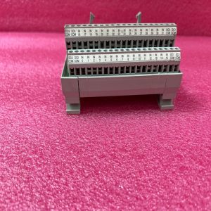
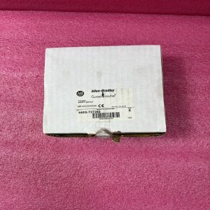
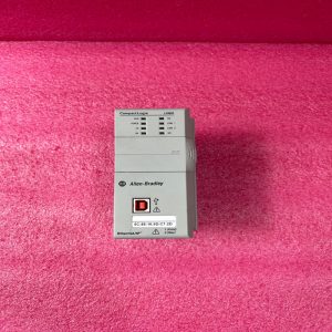
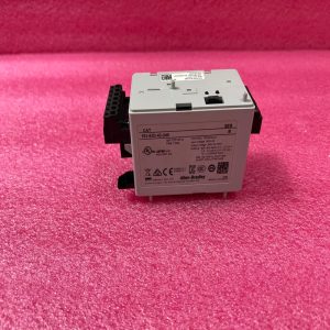
Brand:Allen-Bradley Model number:1762-OW8
Colour:new Warranty: 12 months
Lead Time:3-day working day Country of origin: United States
Price: Please contact us Product weight:1.5kg
Product Dimensions:
Wiring the Finger-Safe Terminal Block
When wiring the terminal block, keep the finger-safe cover in place.
1. Route the wire under the terminal pressure plate. You can use the stripped end of the wire or
a spade lug. The terminals will accept a 6.35 mm (0.25 in.) spade lug.
2. Tighten the terminal screw making sure the pressure plate secures the wire. Recommended
torque when tightening terminal screws is 0.904 Nm (8 lb-in).
Wire Size and Terminal Screw Torque
Each terminal accepts up to two wires with the following restrictions:
TIP If you need to remove the finger-safe cover, insert a screw driver into one of the
square wiring holes and gently pry the cover off. If you wire the terminal block
with the finger-safe cover removed, you will not be able to put it back on the
terminal block because the wires will be in the way.
Wire Type Wire Size Terminal Screw Torque
Solid Cu-90 °C (194 °F) 14…22 AWG 0.904 Nm (8 lb-in.)
Stranded Cu-90 °C (194 °F) 16…22 AWG 0.904 Nm (8 lb-in.)
Panel Mounting
Use the dimensional template shown below to mount the module. The preferred mounting
method is to use two M4 or #8 panhead screws per module. M3.5 or #6 panhead screws may also
be used, but a washer may be needed to ensure a good ground contact. Mounting screws are
required on every module.
TIP For environments with greater vibration and shock concerns, use the panel
mounting method described below, instead of DIN rail mounting.
End Anchor
End Anchor
MicroLogix 1200
Controller
MicroLogix 1200
Expansion I/O
MicroLogix 1200
Expansion I/O
MicroLogix 1200
Expansion I/O
90
(3.54)
100
(3.94)
40.4
(1.59)
40.4
(1.59) 14.5
(0.57)
For more than 2 modules: (number of modules – 1) x 40 mm (1.58 in.)

Shipping Port: Xiamen, China
Payment: Bank of Chicago, Bank of Singapore
Express cooperation: fedex, DHL, UPS and your express account
Service: Professional Sales provides 24 hours /7 days online service
Please make an inquiry for more models:
AB 1747-L532/D
AB 1747-L532/D/E
AB 1747-L532/E
AB 1747-L533
AB 1747-L541
AB 1747-L541/B
AB 1747-L541/B/C
AB 1747-L541/C
AB 1747-L542
AB 1747-L542/B
AB 1747-L542/C
AB 1747-L543
AB 1747-L543/C
AB 1747-L55
AB 1747-L551
AB 1747-L551/B
AB 1747-L551/C
AB 1747-L552
AB 1747-L552/C
AB 1747-L553
AB 1747-L553/B
AB 1747-L553/C
AB 1747-M1
AB 1747-M11
AB 1747-M12/A
AB 1747-M13
AB 1747-M15
AB 1747-M2
AB 1747-M4
AB 1747-NI4
AB 1747-PSD
AB 1747-SCNR
AB 1747-SDN
AB 1747-SN
AB 1747-SN17
AB 1747-UIC
AB 1756-0B16E
AB 1756-0F4
AB 1756-0X8I
AB 1756-A10
AB 1756-A13
AB 1756-A17
AB 1756-A4
AB 1756-A7
AB 1756-BA11
AB 1756-BA2
AB 1756-CFM
AB 1756-CN2
AB 1756-CN2/B
AB 1756-CN21
AB 1756-CN2R
AB 1756-CN2R/B
AB 1756-CNB
AB 1756-CNB/A/B/C/D
AB 1756-CNB/D
AB 1756-CNB/E
AB 1756-CNBR
AB 1756-CNBR/A/D
AB 1756-CNBR/D
AB 1756-CNBR/E
AB 1756-CPR2
AB 1756-DHRIO
AB 1756-DHRIO/C
AB 1756-DHRIO/D
AB 1756-DHRIO/E
AB 1756-DMD30
AB 1756-DNB
AB 1756-DNB/A
AB 1756-DNB/A/B
AB 1756-DNB/B