Description
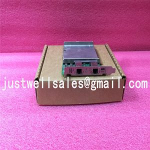
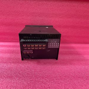
ADV161-P00-S2 YOKOGAWA DIGITAL INPUT MODULE
Product Dimensions:
GENERAL
This GS covers the hardware specifications of the Digital I/O Modules (FIO) that can be installed in the ESB Bus
Node Unit (ANB10S, ANB10D), Optical ESB Bus Node Unit (ANB11S, ANB11D), the ER Bus Node Unit (ANR10S,
ANR10D) and the Field Control Unit (AFV30S, AFV30D, AFV40S, AFV40D, AFF50S, AFF50D, AFV10S, AFV10D).
STANDARD SPECIFICATIONS
Digital Input Modules
The Digital Input Modules receive 32-channel or 64-channel 24 V DC ON/OFF signals.
The ADV151 and ADV161 can be used in dual redundant configuration.
Item Specifications
Model ADV151-P/ADV151-E (*1) ADV157 ADV161
Number of input channels 32 32 64
Rated input voltage (*2) 24 V DC (sink/source) 24 V DC (sink/source) 24 V DC (sink/source)
Input ON voltage 18 to 26.4 V DC 18 to 26.4 V DC 20 to 26.4 V DC
Input OFF voltage 5.0 V DC or less 5.0 V DC or less 5.0 V DC or less
Input current (at rated input voltage) 4.1 mA±20 % / channel 4.1 mA±20 % / channel 2.5 mA±20 % / channel
Maximum allowable input voltage 30.0 V DC 30.0 V DC 30.0 V DC
Withstanding voltage Between input signal and system: 2 kV AC, For 1 minute
Between commons: 500 V AC, For 1 minute, common every 16-channel (*3)
Functions
Status input Function for detecting
ON/OFF status
Function for detecting
ON/OFF status
Function for detecting
ON/OFF status
Pushbutton input Function for counting the
pushbutton edges
— Function for counting the
pushbutton edges
Input response time 8 ms or less (for status input)
Minimum ON detection time 20 ms (for pushbutton input)
Maximum ON/OFF cycle 25 Hz (for pushbutton input)
Maximum current consumption 500 mA (5 V DC) 350 mA (5 V DC) 550 mA (5 V DC)
Weight 0.3 kg 0.4 kg 0.3 kg
External connection
Pressure clamp terminal,
Dedicated cable (AKB331),
MIL connector cable
Pressure clamp terminal Dedicated cable (AKB337),
MIL connector cable
*1: ADV151-E cannot be installed in the ER Bus Node Unit.
*2: ADV151, ADV157 and ADV161 are common every 16-channel. All voltage input signals to be connected (24 V DC) must
be in the same polarity.
*3: The withstanding voltage for using a dedicated cable is 500 V AC (between input signal and system).
The withstanding voltage for using MIL connector cable depends on the electrical specifications of its cable.

Shipping Port: Xiamen, China
Payment: Bank of Chicago, Bank of Singapore
Express cooperation: fedex, DHL, UPS and your express account
Service: Professional Sales provides 24 hours /7 days online service
Please make an inquiry for more models:
| YOKOGAWA | CP451-10 S2 |
| YOKOGAWA | F3SP28-3N |
| YOKOGAWA | F3YD64-1A |
| YOKOGAWA | F3NC12-0N |
| YOKOGAWA | DYNASERV SD10ZZZ04 |
| YOKOGAWA | PC10021 |
| YOKOGAWA | BP30-ON |
| YOKOGAWA | SP38-6N |
| YOKOGAWA | SR1008B62-4SN |
| YOKOGAWA | SC200S |
| YOKOGAWA | F3AD04-ON |
| YOKOGAWA | VF701 |
| YOKOGAWA | AMM32 |
| YOKOGAWA | LR 4220E |
| YOKOGAWA | UT2800-1/HB |
| YOKOGAWA | PW301 |
| YOKOGAWA | F3BU06-0N |
| YOKOGAWA | F3LC21-1N |
| YOKOGAWA | F3NC01-0N |
| YOKOGAWA | F3NC02-0N |
| YOKOGAWA | F3PU06-0N |
| YOKOGAWA | F3PU10-0N |
| YOKOGAWA | F3SP21-0N |
| YOKOGAWA | F3WD64-3N |


