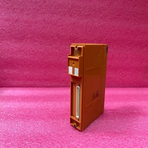
Description
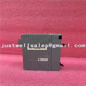
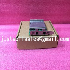
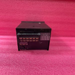
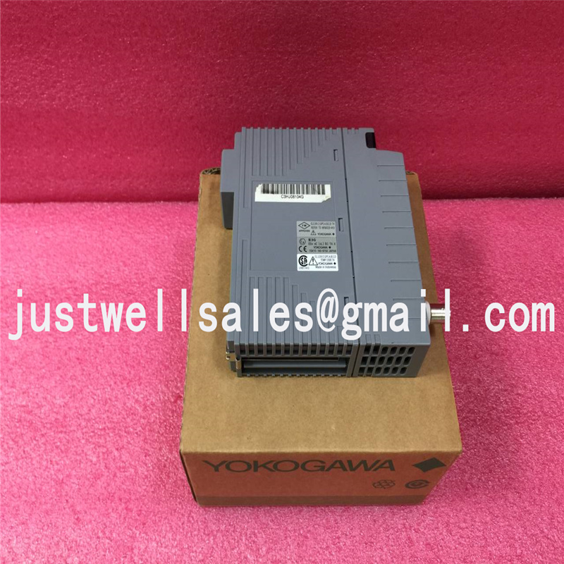
EB501 Yokogawa Central control module
Product Dimensions:
Limitations of Installation under the Ambient Operating Temperature ConditionsWhen the node (-20 to 70 ˚C – optional temperature environment) is to be used under the temperature environment(60 to 70 ˚C), please follow the restrictions below:ANT10U can be used at temperatures from 60 to 70°C without any additional restrictions in the same way as attemperatures from -20 to 50°C.• Max. number of installable input/output modules (IOM): Up to 4 modules can be installed per node.• Make an empty slot (one or more) between SB401, ANT401, ANT411, ANT502, ANT512, EB501 and IOM. Wheninstalling modules with built-in barriers, insulating partition (Part No. T9083NA) must be installed in slot No. 8.• When installing IOM, make an empty slot (one or more) between IOM and IOM.When installing duplexed IOM, make an empty slot (at least two slots) for each duplexed IOM.• Up to 8 relay output modules (ADR541) can be used.• The external load resistance of output channel must be 200 Ω or more when using current IOM (AAI841, AAI835 orAAI543-5, -E(standard response)).• AAI543-6, -F (fast response) cannot be installed.F11E.aiFIOFIOEmptyEmptyFIOEmptyFIOEmptySB401SB401PW48PW48Make an empty slot (one or more)between SB401, ANT502, ANT512, EB501 and IOMDual-RedundantFigure IOM Installation in a NodeNote: When the following modules are installed in a node, the ambient temperature should be 0 to 50 °C.AAP149, AAP849, ADV157, ADV557, ADV161, ADV561, ADV859, ADV159, ADV559, ADV869, ADV169, ADV569,ALR111, ALR121, ALE111, ALF111, ALP111, ALP121When AAI543-6, -F (fast response) is installed in a node, the ambient temperature should be 0 to 60 °C.l Limitations of Installation for AAT141 (the combination of Thermocouple input and Pressureclamp terminal)To keep the reference junction compensation accuracy, make sure to meet the following conditions. The pressureclamp terminal should not be affected by radiated heat,For details of the reference junction compensation accuracy, refer to “Analog I/O Modules” (GS33K50F60-50E).Specifications for node only• Do not install a heat-radiating unit beneath the AAT141 installed node.• Do not install AAT141 in the place where airflow affects directly.• Do not install an AAT141 next to the CP461 and CP451.• Do not install AAT141 next to the bus interface modules, SB401,ANT502,ANT512 and EB501.• The installable modules in the next to AAT141 are as follows. When installing other than following IOM, make anempty slot (one or more ) in each side.Installable modules: AAT141, AAT145, AAR181,AAR145, AAV141, AAV142, AAV542Installation in Cabinet If there is a fan in the upper space of the cabinet, install the module in a position that is 3 units (1 unit = 44.45 mm)lower than the fan.• Do not install an AAT141 next to the CP461 and CP451.• Do not install AAT141 next to the bus interface modules, SB401, ANT502, ANT512 and EB501.• The installable modules in the next to AAT141 are as follows. When installing other than following IOM, make anempty slot (one or more ) in each side. Installable modules: AAT141, AAT145, AAR181, AAR145, AAV141, AAV142,AAV542• When installing AAT141 to AFV40 or ACB51, it should be installed to the following positions (3, 4, 5, 7, 8, 9, 10) asshown in the figure below.• At the positions of 6, 11 and 12, the heat-generating devices should not be installed.• Moreover, the node that AAT141 is installed should not be placed above or under the node fan unit.Field wiringNominal conductor cross-sectional area of this module is 1.25 mm2 or less. Connect to from the CH1 of terminal.Note: The reference junction compensation accuracy is for when the temperature environment is in stability condition. If thetemperature environment is varied, accuracy error may occur until the temperature becomes stability condition.
Shipping Port: Xiamen, China
Payment: Bank of Chicago, Bank of Singapore
Express cooperation: fedex, DHL, UPS and your express account
Service: Professional Sales provides 24 hours /7 days online service
Please make an inquiry for more models:
| YOKOGAWA | CP451-10 S2 |
| YOKOGAWA | F3SP28-3N |
| YOKOGAWA | F3YD64-1A |
| YOKOGAWA | F3NC12-0N |
| YOKOGAWA | DYNASERV SD10ZZZ04 |
| YOKOGAWA | PC10021 |
| YOKOGAWA | BP30-ON |
| YOKOGAWA | SP38-6N |
| YOKOGAWA | SR1008B62-4SN |
| YOKOGAWA | SC200S |
| YOKOGAWA | F3AD04-ON |
| YOKOGAWA | VF701 |
| YOKOGAWA | AMM32 |
| YOKOGAWA | LR 4220E |
| YOKOGAWA | UT2800-1/HB |
| YOKOGAWA | PW301 |
| YOKOGAWA | F3BU06-0N |
| YOKOGAWA | F3LC21-1N |
| YOKOGAWA | F3NC01-0N |
| YOKOGAWA | F3NC02-0N |
| YOKOGAWA | F3PU06-0N |
| YOKOGAWA | F3PU10-0N |
| YOKOGAWA | F3SP21-0N |
| YOKOGAWA | F3WD64-3N |


